Electronics getting too hot and failing? Relying on inadequate cooling leads to big problems. I’ve seen firsthand how crucial effective thermal management is.
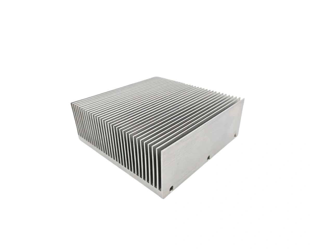
Based on my years manufacturing components at ALUT, I believe a superior heat sink with fins is often the ultimate cooling secret because its extended surfaces dramatically increase the area for heat to escape. We find this design efficiently moves heat away from critical components, preventing overheating.
This simple yet powerful concept is fundamental to modern electronics. But how does a heat sink with fins actually work, and what makes it so effective? Let’s explore.
How does a heat sink with fins transfer heat effectively?
Ever wonder how those metal fins keep your devices from frying? Simply hoping heat will disappear isn’t a strategy. As an engineer, the physics of this always intrigues me.
From my manufacturing experience at ALUT, I know a heat sink with fins transfers heat effectively through two main processes. First, heat conducts from the hot component into the base and up into the fins. Then, the fins convect this heat into the cooler surrounding air.
A heat sink with fins operates based on fundamental principles of thermodynamics to move thermal energy from a hot source (like a CPU, LED, or power transistor) to a cooler ambient environment, typically air. This effective transfer relies primarily on two modes of heat transfer: conduction and convection.
1. Conduction: The Internal Heat Path
The first stage of heat transfer within the cooling assembly itself is conduction.
Heat Source Contact: The base of the heat sink with fins is placed in direct physical contact with the heat-generating component. To maximize this contact and minimize tiny air gaps (which are poor heat conductors), a Thermal Interface Material (TIM) like thermal grease or a thermal pad is almost always used.
Heat Spreading in Base: Heat flows from the component into the base of the heat sink. The base material, typically aluminum or copper, needs high thermal conductivity to allow the heat to spread out rapidly and uniformly across its area.
Heat Flow into Fins: From the base, heat then conducts up the length of each individual fin. The fins are designed to be relatively thin to minimize thermal resistance along their length but thick enough to provide structural integrity. The rate of conduction into and along the fins is critical for overall performance.
2. Convection: Heat Escape to the Environment
Once the heat has spread into the fins, the next step is to transfer it to the surrounding air. This is where the “fins” part of a heat sink with fins becomes crucial.
Maximizing Surface Area: The primary role of the fins is to dramatically increase the surface area that is exposed to the cooler ambient air. Without fins, only the relatively small area of the baseplate would be available for this heat exchange, which would be very inefficient for most electronic components.
Convective Heat Transfer Process: Air molecules come into contact with the heated surfaces of the fins. Heat energy is transferred from the hotter fin surface to these cooler air molecules, which then carry the heat away. This process is called convection.
Factors Influencing Convection: The efficiency of convective heat transfer from a heat sink with fins depends on:
The temperature difference between the fin surface and the ambient air.
The total surface area of the fins.
The airflow velocity over the fins (natural convection vs. forced convection with a fan).
The properties of the air itself.
The design of the fins – their height, thickness, spacing (pitch), and shape – is engineered to optimize this convective process for a given application.
What is the main purpose of a heat sink with fins?
Just a piece of metal with some spikes, right? It might look simple, but its purpose is critical for modern technology. I’ve seen devices fail without proper cooling, and often a heat sink with fins is the solution.
Based on my work at ALUT helping clients design cooling solutions, I assert the main purpose of a heat sink with fins is to prevent electronic components from exceeding their safe operating temperatures. It achieves this by efficiently dissipating the waste heat they generate during operation into the surrounding environment.
The primary and most crucial purpose of a heat sink with fins is thermal management. Specifically, it is designed to facilitate the dissipation of unwanted heat generated by electronic or mechanical components, thereby maintaining their operating temperature within safe and optimal limits. Without effective heat dissipation, many modern devices would quickly overheat, leading to performance degradation, reduced lifespan, or catastrophic failure.
Preventing Overheating and Its Consequences
Electronic components, such as microprocessors (CPUs, GPUs), power transistors, LEDs, and many types of integrated circuits, generate heat as a byproduct of their operation due to electrical resistance. If this heat is not removed effectively:
Component Temperature Rises: The internal temperature of the component will increase.
Performance Degradation: Most semiconductor devices have optimal operating temperature ranges. Exceeding these can lead to slower processing speeds, glitches, or incorrect operation.
Reduced Lifespan: Prolonged exposure to high temperatures accelerates material degradation and electromigration within chips, significantly shortening the component’s useful life. This is a major concern for product reliability.
Thermal Runaway: In some cases, increased temperature can lead to increased current draw, which generates even more heat, creating a dangerous cycle that can destroy the component.
System Instability: Overheating of one component can affect the stability and performance of the entire system it is part of.
How a Heat Sink with Fins Achieves This Purpose
The heat sink with fins addresses this challenge by providing an enhanced pathway for heat to escape from the hot component to the cooler ambient environment.
Efficient Heat Collection: The base of the cooling assembly makes good thermal contact with the heat source, drawing heat away.
Increased Dissipation Area: The fins dramatically increase the surface area available for heat to transfer to the air via convection. Air is a relatively poor thermal conductor, so a large surface area is essential for effective heat exchange. A simple flat plate without fins would have a much smaller area and thus much poorer cooling capability.
Facilitating Airflow: The design and spacing of the fins are intended to allow air (either natural or fan-forced) to flow between them, constantly carrying away the dissipated heat and bringing in cooler air.
Therefore, the main purpose of using a heat sink with fins is to ensure the reliability, longevity, and optimal performance of heat-generating components by effectively managing their thermal load. It’s a critical enabler for the high-density and high-power electronics we rely on daily.
What materials are ideal for a heat sink with fins?
Does it matter what metal these are made from? Absolutely. The material choice directly impacts how well a heat sink with fins performs its crucial cooling task, and I’ve seen the difference it makes in product longevity.
From my experience manufacturing thermal solutions at ALUT, I know the ideal materials for a heat sink with fins must possess high thermal conductivity. Aluminum alloys are very common due to their good conductivity, light weight, and cost-effectiveness. Copper is used for higher performance needs, despite its greater weight and cost.
The selection of material for a heat sink with fins is a critical design decision, as it directly influences the component’s thermal performance, weight, cost, and manufacturability. The most important property for a heat sink material is high thermal conductivity, which dictates how efficiently heat can be conducted from the baseplate and throughout the fins.
Key Material Properties
Thermal Conductivity (k): Measured in Watts per meter-Kelvin (W/m·K), this indicates a material’s ability to conduct heat. Higher values are better.
Density (ρ): Lower density means a lighter heat sink, which is important for weight-sensitive applications.
Specific Heat Capacity (c): Ability to absorb heat. Less critical for steady-state heat dissipation but can play a role in transient scenarios.
Cost: Material cost is a significant factor in overall product cost.
Manufacturability: The ease with which the material can be formed into complex finned shapes (e.g., via extrusion, casting, stamping, machining).
Corrosion Resistance: Important for long-term durability, especially in harsh environments.
Common Materials Used
Aluminum Alloys:
Characteristics: Aluminum is by far the most common material for a heat sink with fins. Alloys like 6061 and 6063 offer an excellent balance of good thermal conductivity (around 160-200 W/m·K), light weight (density ~2.7 g/cm³), good strength, excellent manufacturability (especially for extrusion), and relatively low cost.
Advantages: Cost-effective, lightweight, easily extruded into complex profiles, good corrosion resistance (especially when anodized).
Disadvantages: Lower thermal conductivity than copper.
Advantages: Superior thermal performance, making it suitable for very high heat loads or compact designs where maximum dissipation is needed.
Disadvantages: Much heavier than aluminum (density ~8.96 g/cm³), significantly more expensive, and harder to extrude or machine. Often used for the baseplate in combination with aluminum fins (to combine copper’s spreading ability with aluminum’s fin efficiency and lower weight) or for very high-performance, smaller components.
Other Materials (Less Common for general purpose heat sinks with fins):
Graphite: Certain engineered graphite materials offer very high thermal conductivity (can exceed copper in specific orientations) and are extremely lightweight. However, they are more brittle and expensive.
Composite Materials: Metal matrix composites (e.g., aluminum-silicon carbide) can offer tailored thermal properties but are usually reserved for specialized, high-cost applications.
Material Comparison Table
素材
Thermal Conductivity (W/m·K) (Approx.)
Density (g/cm³) (Approx.)
Relative Cost
Key Advantage for Heat Sink with Fins
Aluminum (6063)
~200
~2.7
低い
Best overall balance of performance, cost, weight
Aluminum (6061)
~170
~2.7
低い
Good strength, machinability
Copper (C11000)
~390
~8.9
高い
Highest thermal conductivity
Graphite (Eng.)
200-1500+
~1.8-2.2
非常に高い
Very high conductivity, lightweight
The choice often comes down to balancing the required thermal performance against cost and weight constraints. For the vast majority of applications requiring a heat sink with fins, aluminum alloys provide the optimal solution.
How can you improve heat sink with fins performance?
Is your current cooling solution just not cutting it? There are ways to get more out of a heat sink with fins without a complete redesign. I often advise clients on these optimization techniques to prevent costly overheating issues.
Based on our work in thermal management at ALUT, I find you can improve heat sink with fins performance significantly by optimizing airflow with a fan, ensuring good thermal contact with the heat source using quality TIM, increasing the overall surface area through fin design, and selecting materials with higher thermal conductivity.
Maximizing the thermal performance of a heat sink with fins involves optimizing various aspects of its design, the materials used, and its interaction with the surrounding environment. Even small improvements can lead to significant temperature reductions for the heat-generating component. Here are several key strategies:
1. Enhance Airflow (Forced Convection)
Add a Fan: The single most effective way to boost performance is often to introduce forced airflow using a fan. A fan increases the convective heat transfer coefficient significantly by constantly replacing the hot air layer near the fins with cooler ambient air.
Optimize Fan Placement: Position the fan to ensure airflow is directed effectively through the fin channels. Consider push vs. pull configurations.
Reduce Airflow Impedance: Ensure that the fin pitch (spacing) and design do not unduly restrict airflow, especially when relying on a fan. If fin spacing is too tight for the fan’s static pressure capability, air will bypass the heat sink.
Ducting: In some systems, ducting can be used to channel all available airflow directly through the heat sink with fins, preventing bypass and maximizing efficiency.
2. Improve Thermal Interface
Use High-Quality Thermal Interface Material (TIM): The TIM (thermal grease, pad, phase change material) between the heat source and the heat sink base is critical. A good TIM fills microscopic air gaps, which are poor heat conductors, thereby minimizing thermal resistance at this interface. Ensure proper application (correct thickness, even coverage).
Ensure Good Mounting Pressure: Adequate and even mounting pressure is essential to compress the TIM effectively and ensure intimate contact between the heat sink base and the component.
3. Optimize Fin Design and Surface Area
Increase Surface Area: Generally, more surface area means better heat dissipation. This can be achieved by:
Increasing fin height.
Increasing the number of fins (decreasing fin pitch), up to a point where airflow is not overly restricted.
Adding features to fins (e.g., serrations, waves) to create turbulence and slightly increase surface area, though this can also increase airflow resistance.
Fin Thickness: Thinner fins are generally more efficient (less material for heat to conduct through to the tip, lower weight), but they must be thick enough for structural integrity and to conduct heat effectively from base to tip.
Fin Spacing (Pitch): Needs to be optimized for the airflow conditions. Wider spacing is better for natural convection, while tighter spacing can be used with strong forced airflow.
4. Material Selection
Higher Thermal Conductivity: Using materials with higher thermal conductivity (e.g., switching from aluminum to copper for the baseplate, or using higher-conductivity aluminum alloys) will improve heat spreading and conduction through the heat sink with fins.
5. Surface Treatment
Anodizing (for Aluminum): Black anodizing can slightly improve radiative heat transfer, especially in natural convection or vacuum environments, although its effect on convective transfer is minimal. However, a thick anodized layer can also add thermal resistance.
By systematically addressing these factors, the performance of a heat sink with fins can be significantly enhanced, allowing for cooler operation of electronic components and improved system reliability.
結論
A heat sink with fins is a vital, effective cooling device. Understanding its purpose, materials, and performance factors ensures optimal thermal management for reliable electronics using this essential component.